In the final project we are supposed to demonstrate the ability to synthesize a variety of skills acquired throughout this semester. As discussed in Week 0, I wanted to create a motion-controlled clock-like object that I can use to tell others where I am or what I am doing:
The idea is that when I wave at this "clock", the arm or pointer will turn to the desired location and stop. I want to create an object like this because a lot of my friends have been very curious about my weekly projects but I've hardly had time to do a "show and tell" for them. With this "clock" on my door, when I am not around, they can find out where I am and see a vivid example of what I've learned from this class.
On this page I am documenting the creation process of this object. If you need to go to a specific section, please click on the the following hyperlinks. Otherwise, please keep scrolling down to see my entire workflow.
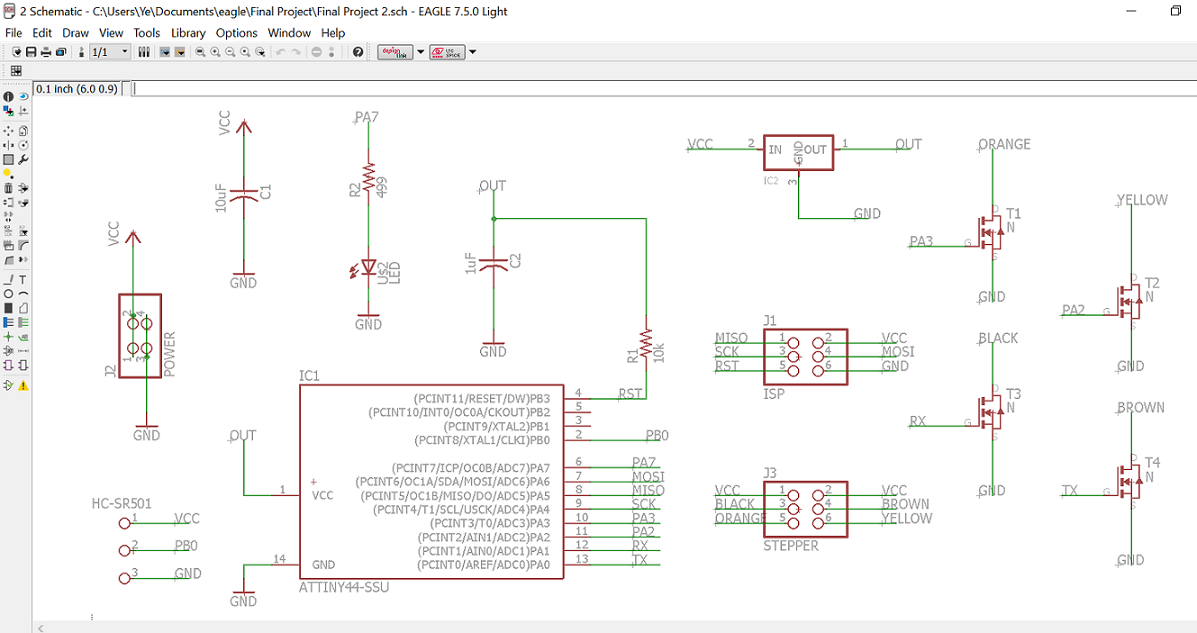
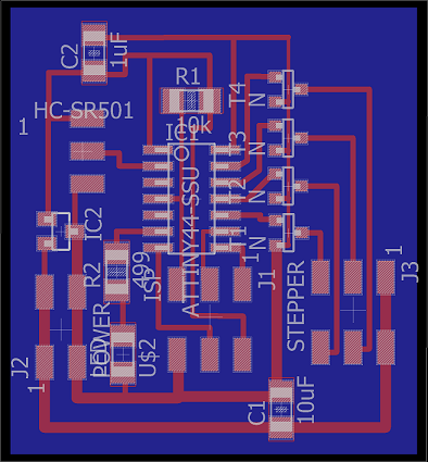
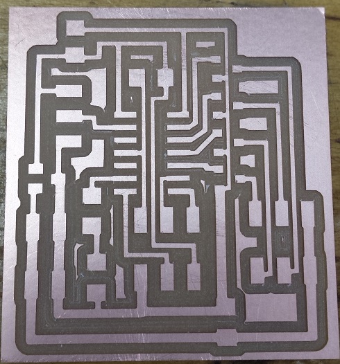
I started off with designing the board by combining my boards from the input and output device weeks. Rob helped me figure out which components to keep and which ones to remove. I have decided to keep the LED on my PIR motion sensor board. The LED lights up whenever the motion sensor detects motion; this will help me decide if the motion sensor is working and troubleshoot the board later if I need to. Here are the schematic and board views, the traces and the border of my board:

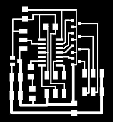
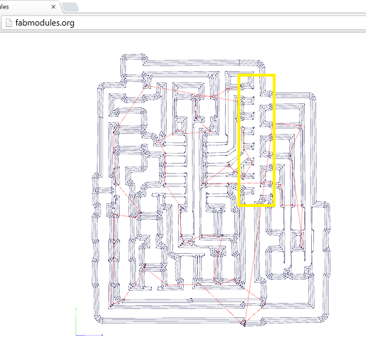
When I first tried to mill the board, there some traces that were not cut out properly:
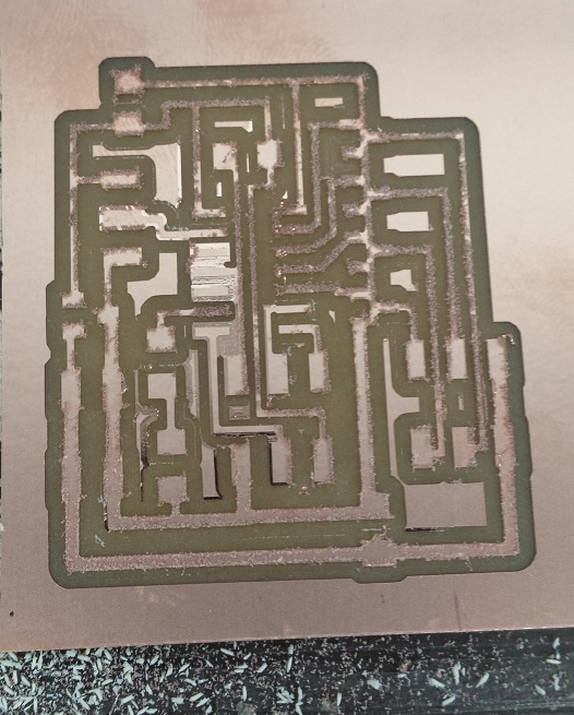
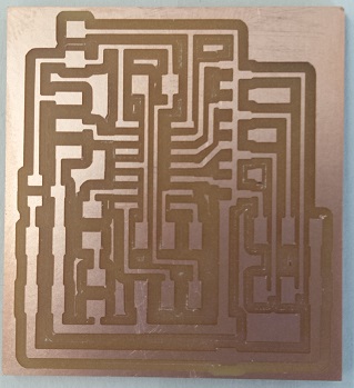
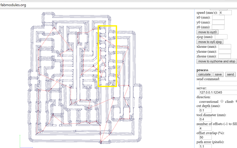
Rob suggested changing the cut depth of the 1/64" endmill from 0.1mm to 0.15mm on FabModules, and this solved the problem.
As I was stuffing this board I realized that all three legs of all the N-channel mosfets are attached to ground by mistake. So I had to go back to adjust the width of the ground trace and mill another board:
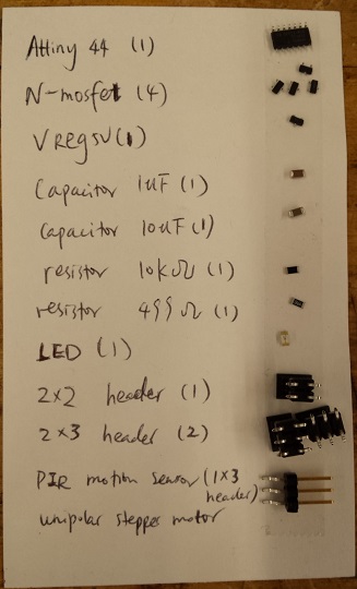
Here are the corrected board, the list of components that I used and the stuffed board:
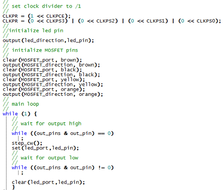
Then I combined Neil's C code for the unipolar stepper motor and the PIR motion sensor to create my own code. Tiffany helped me create the appropriate .make file. The .c and .make files are attached to the end of this section. Here is a picture of the very simple C code in the main loop:
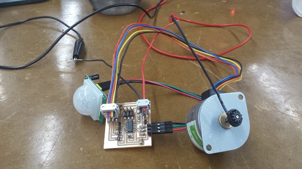
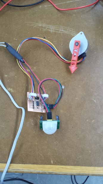
As I tried to program my board using FabISP I received the "rc=-1" error again. Since I have seen this error in Week 11, I changed the Attiny44 microcontroller and the problem was resolved. Here is a video of the input and output devices working together:
As can be seen in the video, each time the motion sensor detects motion, it will send a signal to make the motor turn a 30o-angle clockwise and to light up the LED. When the LED is on, any additional or continuous motion will not cause the motor to make more turns, so one has to wait until the light goes off to wave a second time in order to make another 30o-angle turn.
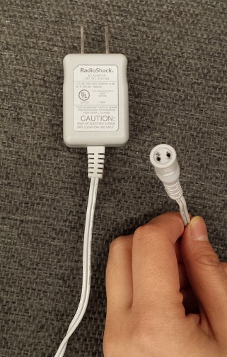
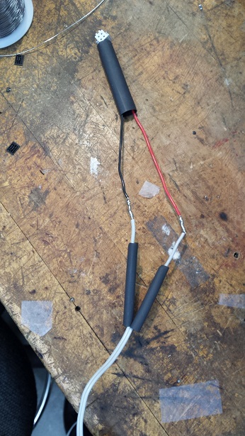
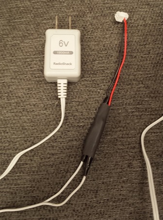
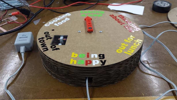
I also found a 6V power supply to power my board. I remember learning how to create custom power supply from Nadya and Rob during the machine project week. I used some heat shrink tubing to wrap the solder joints; but the tubing I used was too big and it didn't shrink as tightly as it should be. So I wrapped some electrical tape around it. Here are some of the pictures:
And here are the .sch and .brd files of my board, as well as the .make and .c files I used to program my board.
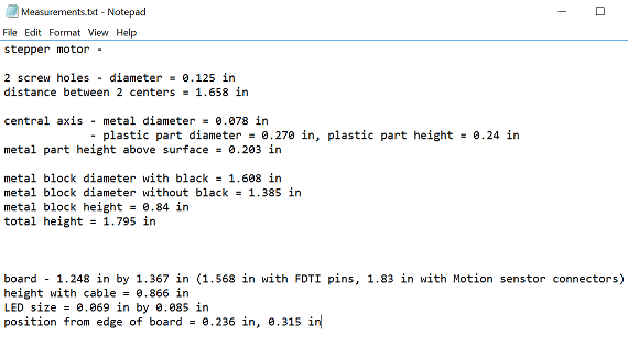
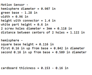
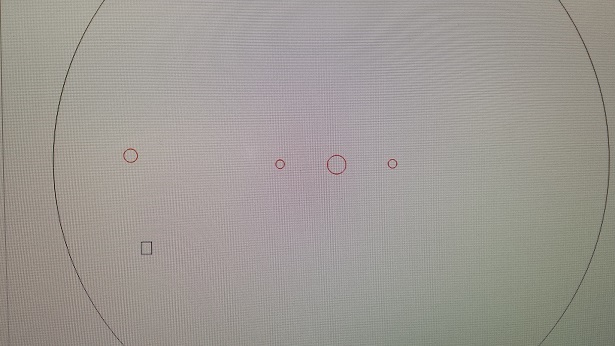
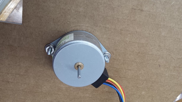
I decided to laser-cut the casing of my "clock" because it is precise and efficient at the same time. I first took some measurements of the motor, the motion sensor and my board:
With these measurements in mind, I designed the first version of the pieces that would make up the casing. The diameter of the "clock" is 8 inches.
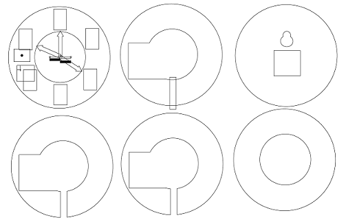
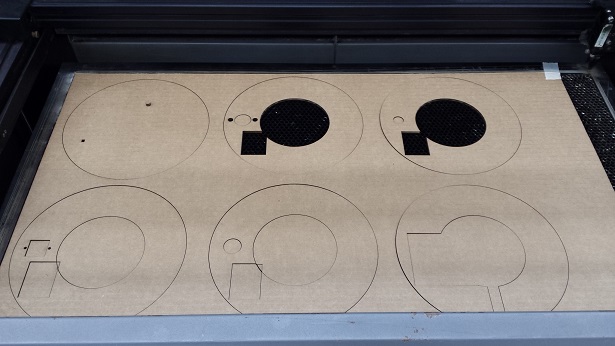
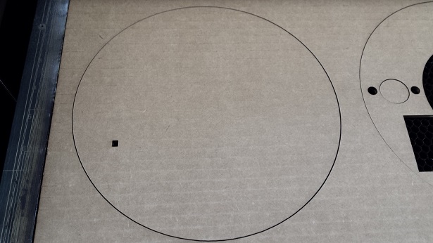
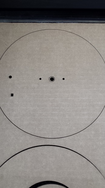
Here are pictures of the laser cutter in action and the first version of the finished cuts:
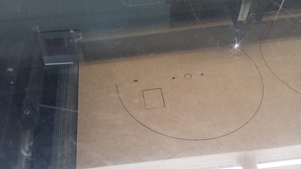
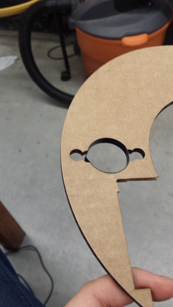
One problem that I encountered is that when I imported the PDF into CarolDraw, the small circles do appear in the software, but the laser cutter wouldn't cut them. So Rob recommended adding new circles in CarolDraw, and that solved the problem.
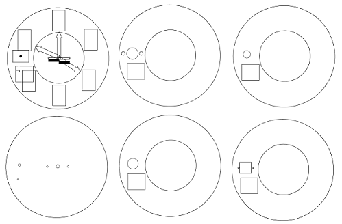
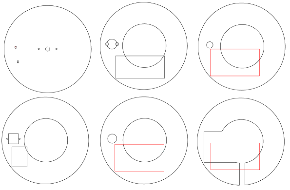
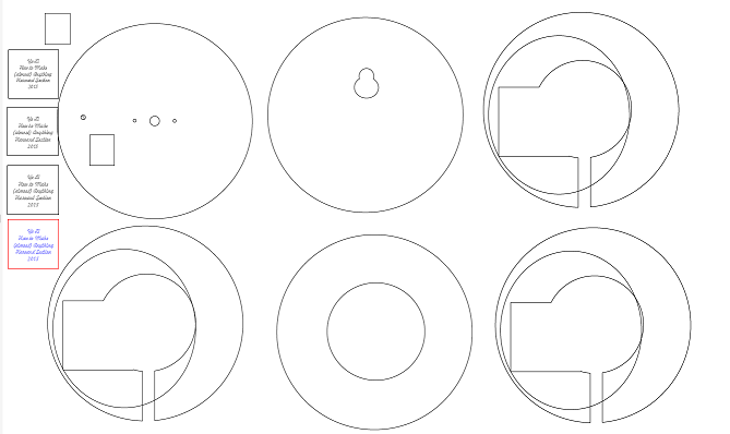
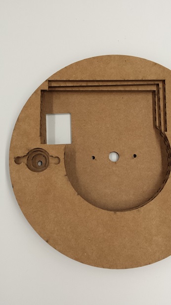
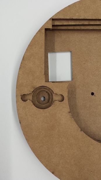
I had to make several adjustments to my original design, as I tried to fit the motor, sensor and board into the casing. Here are the pictures of the final version of my design after taking into account most of the significant modifications:
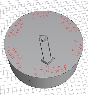
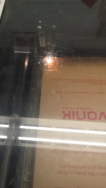
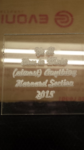
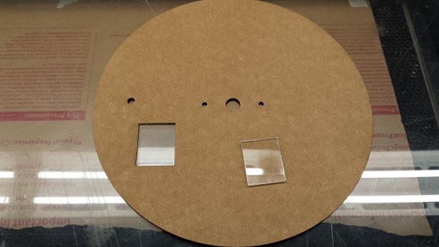
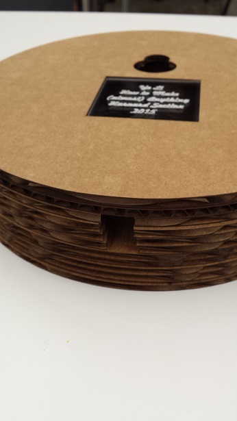
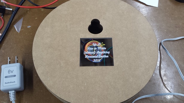
I also wanted my friends to be able to see a bit of the inside of the "clock" after it is closed. So I decided to cut small pieces of acrylic and embed them into the cardboard pieces. I had to cut several pieces to get the size of the acrylic to be slightly bigger than the missing part of the cardboard, so that I could force the acrylic into the cardboard without having to glue them together. I also rastered some words on the piece of acrylic that would appear at the back of the "clock". Here are some of the pictures:
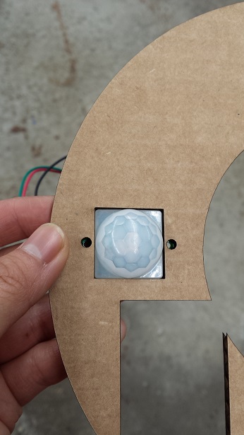
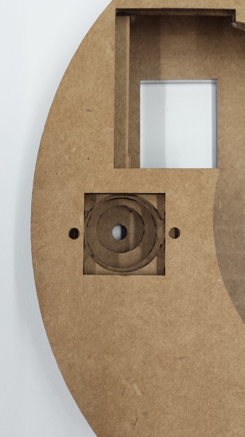
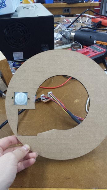
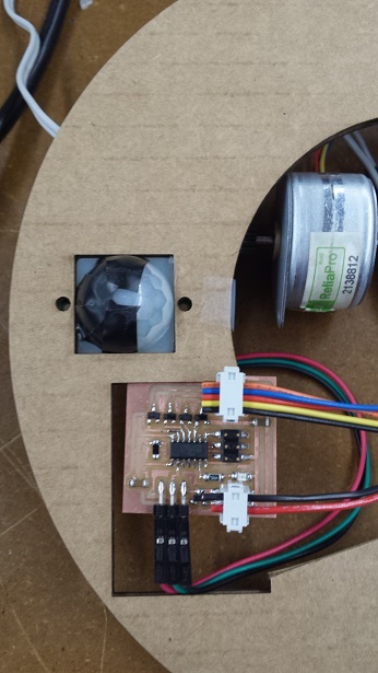
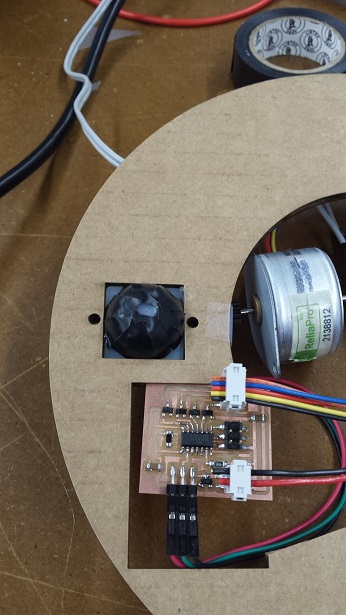
I was very happy to see that the motion sensor fitted perfectly into the cardboard piece:
I used the following settings to cut the cardboard:
And the following settings for the acrylic:
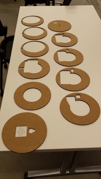
These are all the cardboard pieces:
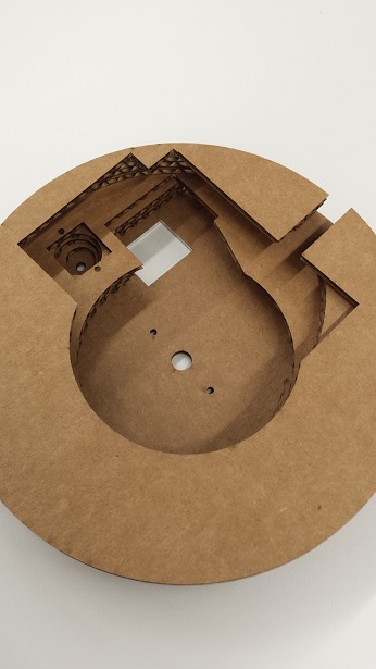
Here are some pictures to show the inner layering:
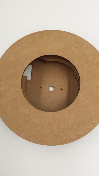
The power cord extends out of the "clock" from the channel:
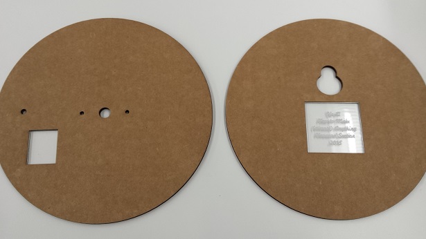
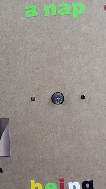
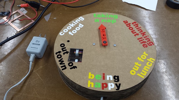
Here is the front of the "clock", the acrylic piece is where my board is located:
Here are the measurements I took and the final design files of the casing.
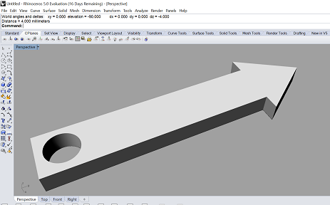
I thought about cutting the pointer of the "clock" and raster the words on the surface with laser cutter, but I wanted the "clock" to have more colors. So I decided to 3D-print the pointer and vinyl cut the words.
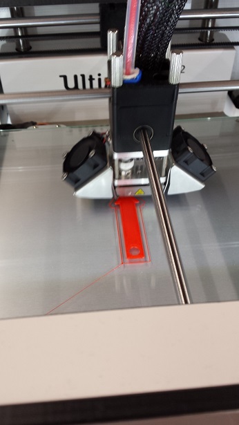
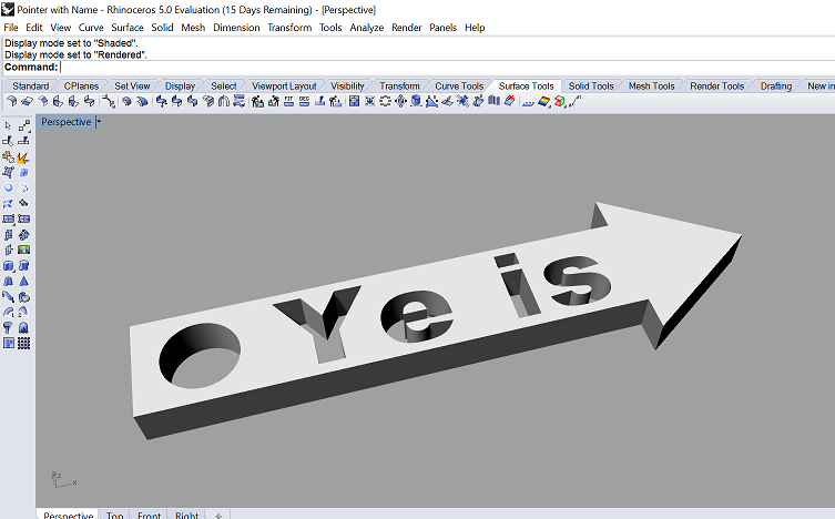
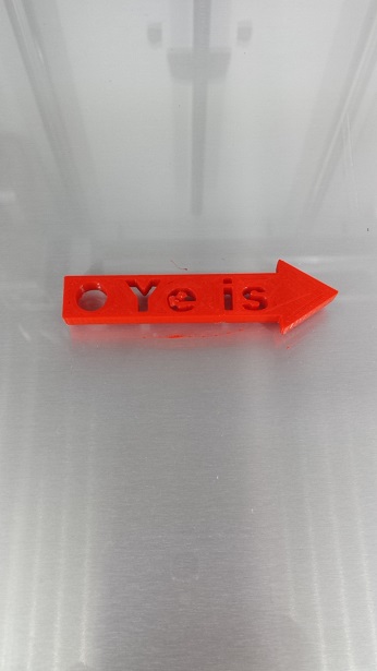
I first designed and printed a simple pointer in Rhino. It is only 6cm long and and 4mm tall. It took about 20 minutes to print it:
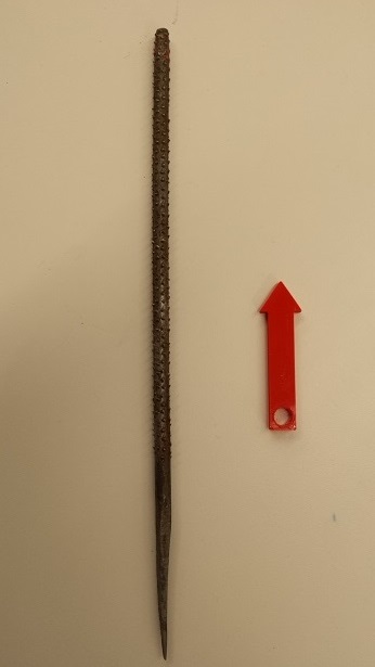
The hole on the pointer was too small for the plastic part of the motor to fit. Jacob helped me file it and make it fit:
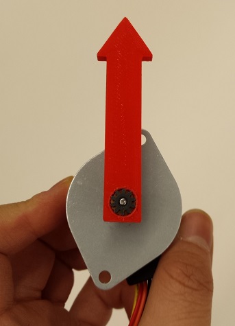
I was going to vinyl cut and paste my name on the pointer; but Justin recommended that I incorporate my name into my pointer design, and that was a great idea:
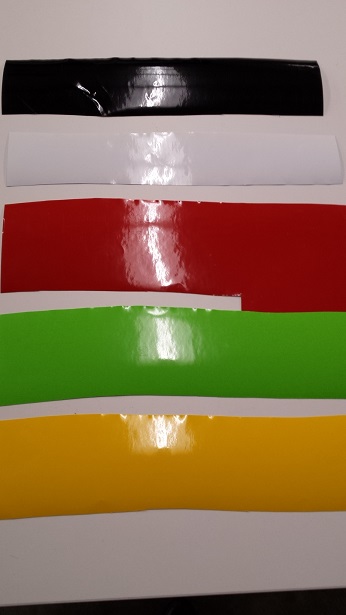
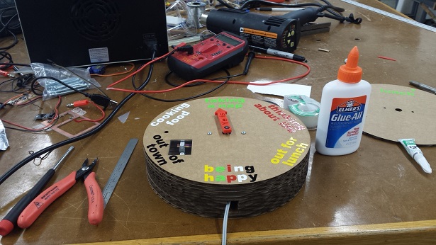
Then I used the vinyl cutter to cut out the words on the "clock". I have used vinyl cutter many times throughout the semester, but never got a chance to document the process. Here's a very useful user guide that someone from the Harvard section wrote on how to use the vinyl cutter and here is a picture of the vinyl I have used:
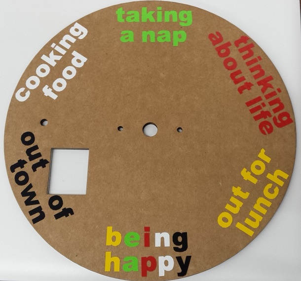
This is how the surface of the "clock" looks like when the words are pasted:
Here are the files for the pointer and the vinyl cuts.
Before assembling everything together I tried to test the electronics one more time with the power supply I made.
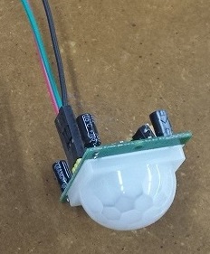
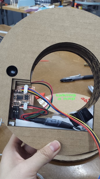
The motion sensor was a bit too sensitive; and I was afraid that anyone who comes close to the "clock" could trigger the pointer to turn. Dan told me that it is possible to adjust the delay time and the sensitivity of the motion sensor. I found this PDF document that describes the motion sensor well. The PDF is also attached here. So I tried to change the delay time and the sensitivity by turning the yellow wheels:
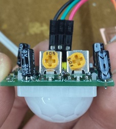
I could not tell the difference between the maximum and the minumum sensitivity, as the sensor appeared to be quite sensative at both extremes. So I decided to set it to the middle. I also set the delay time to be the minimum so that I wouldn't have to wait too long for the LED to go off again. Some of the motion sensor users online suggested putting the sensor into a tubing to narrow its range to one small beam. Since the cardboard pieces have a lot of pores between the top and bottom layers, I decided to cover the majority of the motion sensor and the layers of cardboard around it with black electrical tape to create a casing around the sensor. I also wanted to secure the motion sensor using screws and nuts, but we did not have screws that were small enough; so I decided to glue it on:
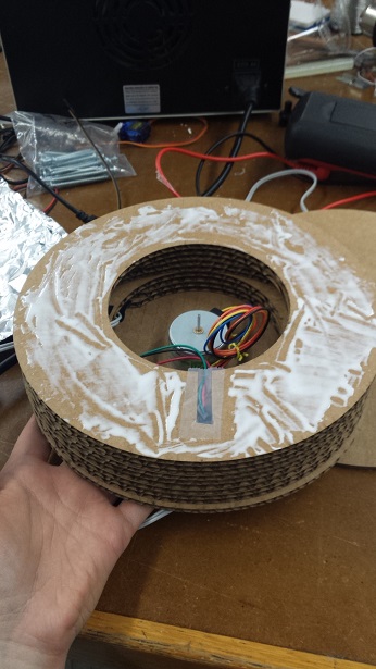
As I glued more layers of the carboard together, I secured the board and the power supply inside with some tapes:
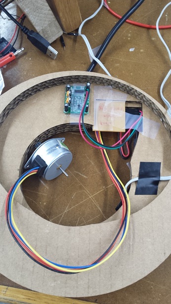
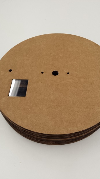
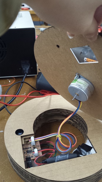
I also attached the motor to the top layer using screws, nuts and washers. The motor fits perfectly into the cardboard piece:
I added the bottom layer and finished the assembly. Here are the tools I've used:
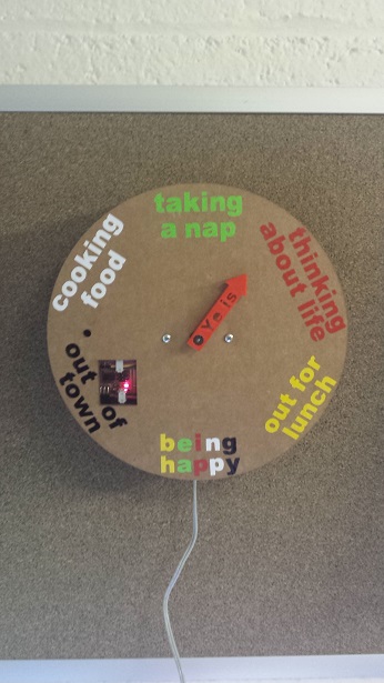
The front, back and side views of the "clock":
The "clock" in action:
In my room I also tried hanging it on the wall. It is still very sensitive but at least it works!

For future improvements, I would certainly look into better ways to reduce the sensitivity of the motion sensor. I could also do more sophisticated things with the code, for example, have the microcontroller count how many times I have waved and do different degrees of turning according to that.
All the materials I used in this project came from the Fab Lab inventory or the Harvard Section shop. Here is a table that outlines the name, quantity and unit list price from the Fab Lab Inventory:
| Name of the Component | Quantity | Unit Price from Fab Lab Inventory |
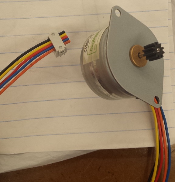
| Unipolar Stepper Motor Step 7 Volt DC-350 mA 7.5 Step Angle 680 G-CM | 1 | $7.95 |
| J-deal® Pyroelectric Infrared PIR Motion Sensor Detector Module Hc-sr501 | 1 | $8.48 |
| ATTINY44A-SSU-ND | 1 | $1.18 |
| MOSFET N-CH 30V 1.7A 3-SSOT | 4 | $0.26 |
| IC 5.0 100MA LDO VREG SOT23 | 1 | $0.32 |
| CAP CER 1UF 50V X7R 10% 1206 | 1 | $0.07 |
| CAP CER 10UF 35V Y5V 1206 | 1 | $0.18 |
| RES 10.0K OHM 1-4W 1% 1206 SMD | 1 | $0.01 |
| RES 499 OHM 1-4W 1% 1206 SMD | 1 | $0.01 |
| LED RED CLEAR 1206 SMD | 1 | $0.13 |
| Bergstik Headers 2X3P UNSHRD HDR 30 microinch gold | 2 | $0.72 |
| Bergstik Headers 2X2P UNSHRD HDR 30 microinch gold | 1 | $0.65 |
| Cardboard (32 inch x 18 inch sheets) | 2 | Less than $1.50 |
| Clear 1/4" thickness 6mm cast material | Very Small Piece | - |
| 3"x2" Single side circuit board stock | 2 | $0.18 |
| Radio Shack 6V/1800mA AC-to-DC Power Adapter | 1 | $14.99 |
I am very thankful for being part of this class. I really appreciate the continuous guidance and support from Neil, Rob and all the teaching fellows. I also wanted to thank all my classmates from Harvard and MIT for making (almost) any amazing thing and for being such a great source of inspiration for me. It's been such a pleasure to work with Rob, Oliver, Vincent, Anya, Nathan, Dan, Sam and the entire Harvard section. Many thanks and all the best with your future endeavors!